Dean H
-
Posts
269 -
Joined
-
Last visited
-
Days Won
31
Content Type
Profiles
Forums
Gallery
Everything posted by Dean H
-
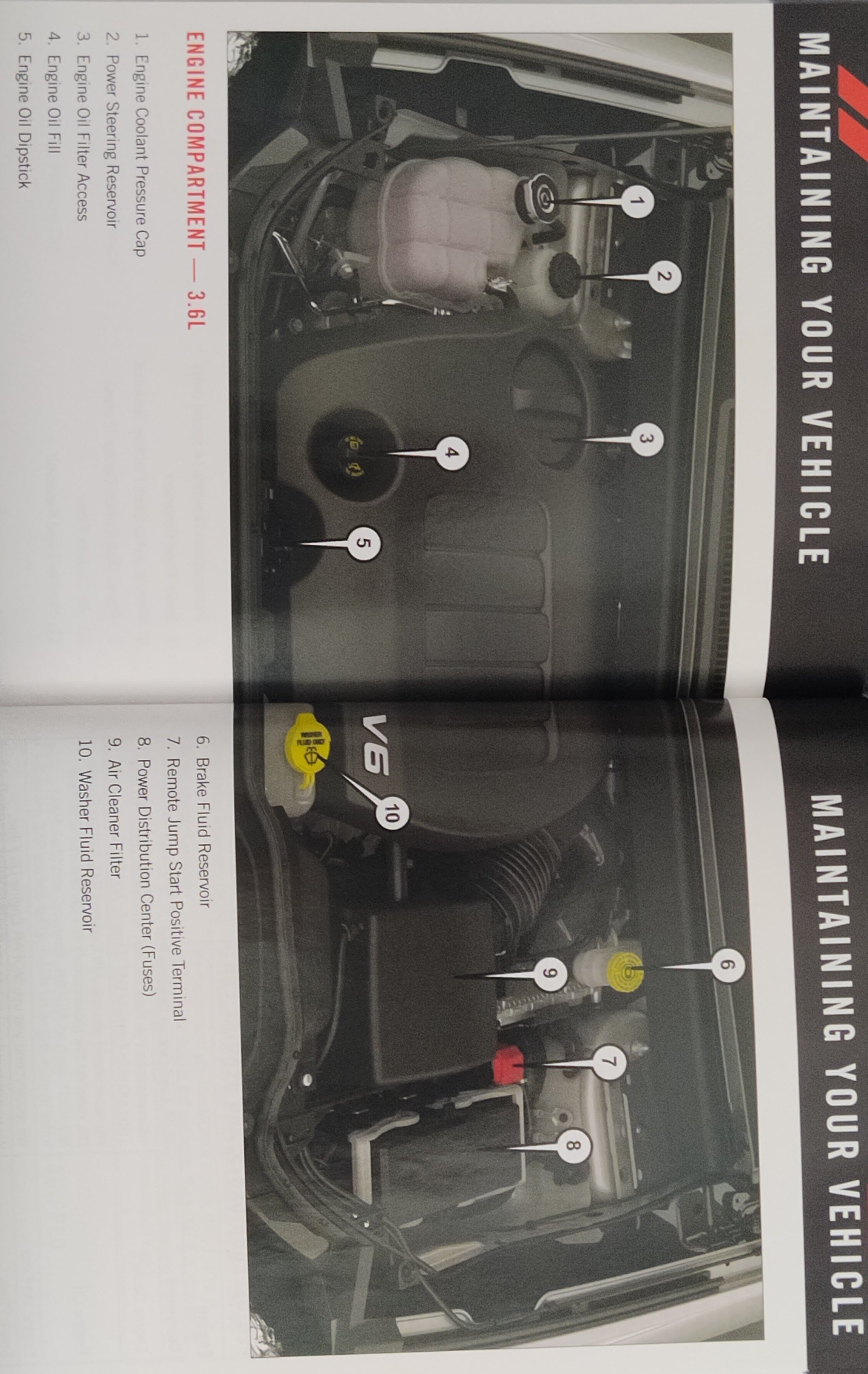
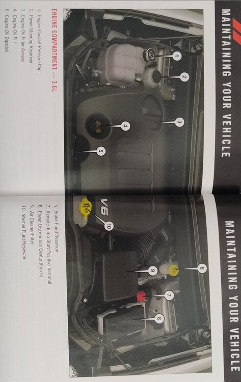
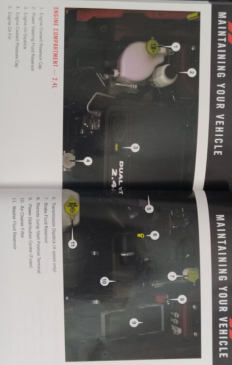
Fluids and basic checks Know what specific type of fluids your year Journey uses. It matters. The reservoir tanks and dip-stick are marked for correct fluid levels. They have yellow caps on them. See pictures at end of this post. 1) coolant level. 2) power steering fluid 3) engine oil 4) brake fluid 5) windshield washer fluid 6) Transmission fluid - if your transmission has the dipstick tube. You will need to buy the dipstick. Read my post and thread here on the Forum. https://www.dodgejourneyforum.com/topic/18151-automatic-transmission-fyi-please-read/ Tire pressure. Consult label on driver's side door jamb. Heater hoses. The Journey has a lot of heater hoses. You should definitely check for leaks. If you have the rear seat AC-Heat controls. There is 2 heater hoses that run from the engine bay. Underneath the passenger floor boards through metal lines to the rear heater core. Then connect to that heater core with rubber hoses. Cabin air filter. Located behind the glove box. EVIC screen located in the center of the instrument cluster. Use the keypad on the left side of the steering wheel. Arrow buttons and the back button. Explore what things you can display on the screen. V6 3.6L engine info. The engine oil filter is located on the top of the engine. Beneath the twist off cap on the engine cover. The oil filter housing and the cap you remove to change it are plastic. If over tightened, the housing will crack and cause an expensive oil leak. Wherever you go for oil changes. You better talk to them so they know all about it. The Journey has a lot of things going on under the hood. That you should monitor and know about. The more often you check your fluids and look around the engine bay. You can catch problems and fix them at your convenience. Before you get stranded somewhere. Dean.
-
Owners manual 2016.

-
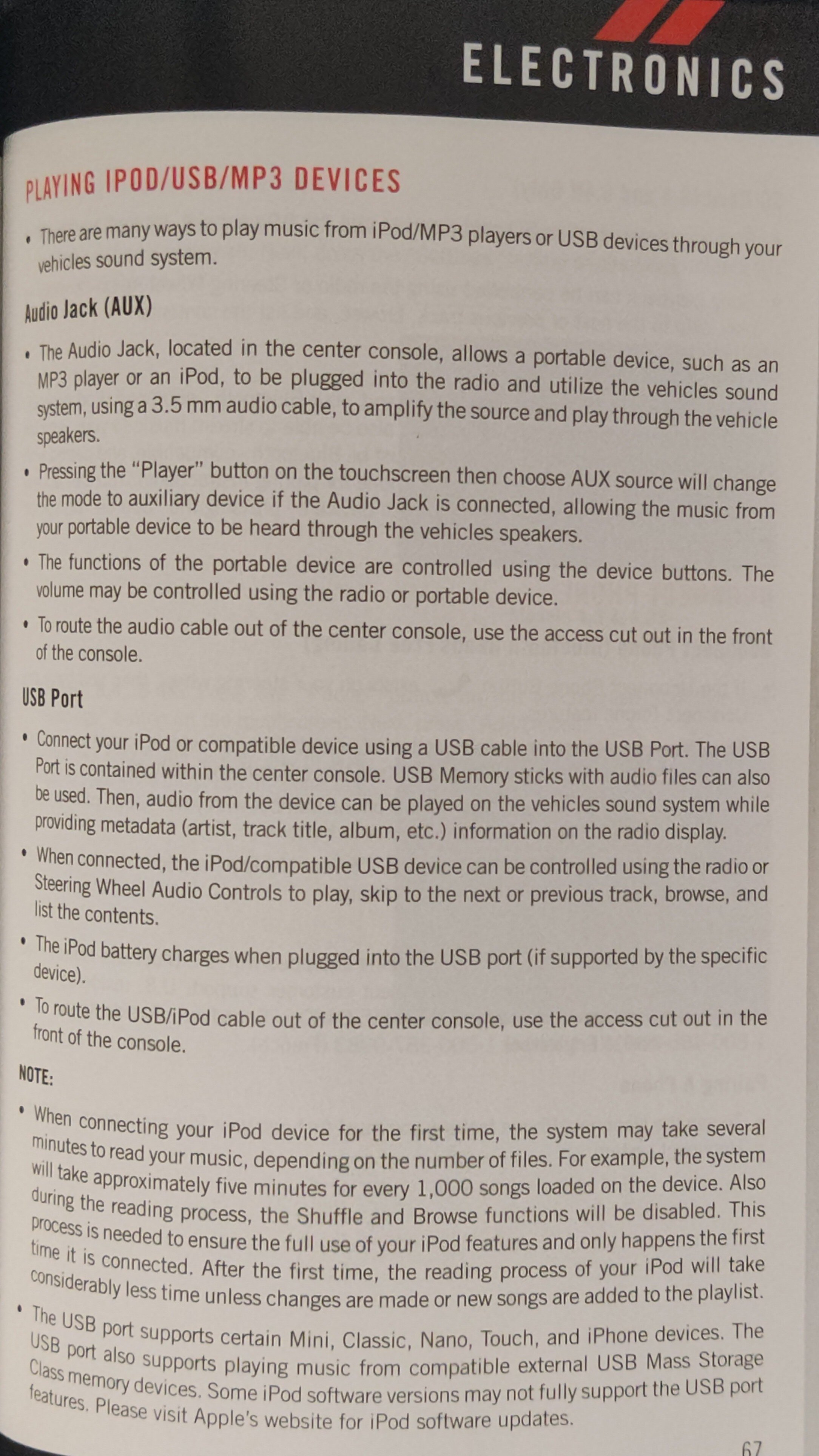
Go with a cigarette lighter-power port adapter to USB.
-
Welcome! First thing, you should do is a correct transmission filter and fluid change. Do not wait. The transmission correct service is often neglected. Dodge recommends 120k miles. Your on borrowed time at that mileage. Here is a post, I put together on everything regarding that. https://www.dodgejourneyforum.com/topic/18151-automatic-transmission-fyi-please-read/
-
Go to Rockautocom. For research it is excellent. Look up your DJ and read through brake pads. Different variables for rotor size and vehicle production date.
-
USB Help Needed
Dean H replied to Jrod423's topic in Audio, Infotainment Navigation, MyGig, UConnect, etc.
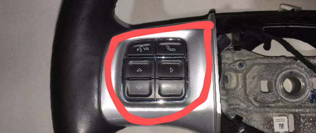
Does your steering wheel have the top 2 keypad buttons as seen in the picture below? The VR button, phone button?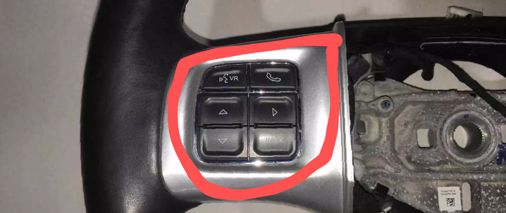
-
Happy to! Do this. For you, get a standard 2 gauge ground cable. Run it from the battery ground stud on the driver's side strut tower to the engine block. The DJ has a weak electrical ground system. Here is my post that explains it entirely. https://www.dodgejourneyforum.com/topic/18374-electrical-system-fyi-ground-system/ Here is my post regarding necessary battery maintenance and upgrades https://www.dodgejourneyforum.com/topic/18210-electrical-system-fyi-battery/ Dean
-
P0171-FUEL SYSTEM 1/1 LEAN Possible Causes RESTRICTED FUEL SUPPLY LINE FUEL PUMP INLET STRAINER PLUGGED FUEL PUMP MODULE 02 SIGNAL CIRCUIT 02 RETURN CIRCUIT 02 SENSOR MAP SENSOR ECT SENSOR ENGINE MECHANICAL FUEL FILTER/PRESSURE REGULATOR POWERTRAIN CONTROL MODULE (PCM)
-
You have an engine vacuum leak. The no power brake booster and these codes are vacuum leak related. Trace vacuum lines from the map sensor to the brake booster and the engine source. P2173- HIGH AIRFLOW/VACUUM LEAK DETECTED (SLOW ACCUMULATION) Possible Causes VACUUM LEAK RESTRICTION IN THE EXHAUST SYSTEM INTERNAL ENGINE MECHANICAL COMPONENTS RESISTANCE IN THE 5-VOLT SUPPLY CIRCUIT RESISTANCE IN THE MAP SIGNAL CIRCUIT RESISTANCE IN MAP SENSOR GROUND CIRCUIT MAP SENSOR POWERTRAIN CONTROL MODULE (PCM)
-
You need to have a bi-directional scan tool. That can communicate with all the modules and test individual components. Perform relearn procedures. I have this one- LAUNCH X431 CRP919EBT Elite... https://www.amazon.com/dp/B0C68BKGN3?ref=ppx_pop_mob_ap_share Please scan for codes and tell me exactly. What they all are right now.
-
When you replace cam position sensors and the throttle body. There is a scan tool relearn function, that has to be done. Start here.
-
Life issues. Say no more, I know. So what all have you replaced so far?
-
If you never did this repair. The BCM is a gateway for all the bus lines. Your in deep. The only person I know of is Ivan in Pennsylvania. https://www.pinehollowdiagnostics.com/
-
OBD code list, can anyone help decipher?
Dean H replied to mamallama's topic in Electrical, Battery & Charging
Tell us everything that has been replaced on your DJ. If you replaced any modules BCM, PCM. They have to have the vehicle vin written to it . -
Remote Start Operating Conditions. In order to operate remote start, the following conditions must be met- Key fob sequence must be operated within a 100 meter range of the vehicle. The vehicle must be in Park Fobik is not in the vehicle The hazard switch off Vehicle Theft Alarm or Panic is not alarming Doors and hood must be closed. The battery voltage is normal (11 to 15 volts). --Remote Start Shut Down/Deactivate Conditions--- Engine will NOT start or will shut down/deactivate during any of the following conditions below. Doors or hood are opened before remote unlock Hazard Switch depressed Panic or theft alam active Brake applied. If the vehicle is remote started and the customer then unlocks and enters the vehicle, the brake application will not stall the vehicle If the vehicle is remote started and no entry is detected, brake application will shut down the engine Low fuel levels, Fuel indicator active A prior remote start cranked the engine, but failed to start the engine. Battery voltage NOT in the normal range. High (run away) or Low Idle (stall) RPM. MIL Active. High Engine Coolant Temperature. Low Engine Oil Pressure.
-
P0128 Thermostat rationality. Theory of Operation- The Thermostat is considered malfunctioning if the coolant temperature does not reach the highest temperature required to enable other diagnostics, or the coolant temperature does not reach a warmed up temperature within 20°F of the Thermostat regulating temperature. The Powertrain Control Module (PCM) creates a model of the engine coolant temperature warm up cycle, based on the engine coolant temperature at start up, ambient temperature, vehicle speed and engine speed. The modeled engine coolant temperature is compared to the Engine Coolant Temperature Sensor reading. If the engine actual temperature reaches the calibrated temperature threshold before the model, the diagnostic passes and completes. If the model reaches the calibrated temperature threshold before the engine actual temperature, a pass/fail determination is made based on the difference between the model and actual values. The diagnostic is considered passing if the difference between the engine actual temperature and model is acceptable when the model is greater than the engine but represents the slowest possible warm-up for a "good" thermostat. When Monitored and Set Conditions When Monitored: This diagnostic runs when the following conditions are met With the engine running. Start up coolant temperature less than 65 deg * C (149 deg * F) Ambient temperature between - B deg * C (17.6 deg * F) and 50 deg * C (122 deg * F) Average vehicle speed greater than (10 coolant temperature reaches 85 deg * C Engine speed does not go above 5400 rpm for more than 32 seconds The pass/fail determination point is reached when the coolant temp model reaches 88 deg * C 190 4°F) Set Conditions: The predicted coolant temperature reaches the target threshold before the actual coolant temperature and the PCM detects that the actual engine coolant temperature is too far below the what is acceptable for a good thermostat Default Actions: MIL. light will illuminate Possible Causes --- LOW COOLANT LEVEL --- COOLING SYSTEM ISSUES --- THERMOSTAT OPERATION
-
Traction control and acceleration lights-poor performance
Dean H replied to samg's topic in Brake, Chassis & Suspension
What code scanner do you have? You need a bi-directional scanner. That is able to communicate with all the systems on the DJ. -
P000D P0018 P0175 P0300 - check your oil first
Dean H replied to DodgeaWrench's topic in Engine & Transmission
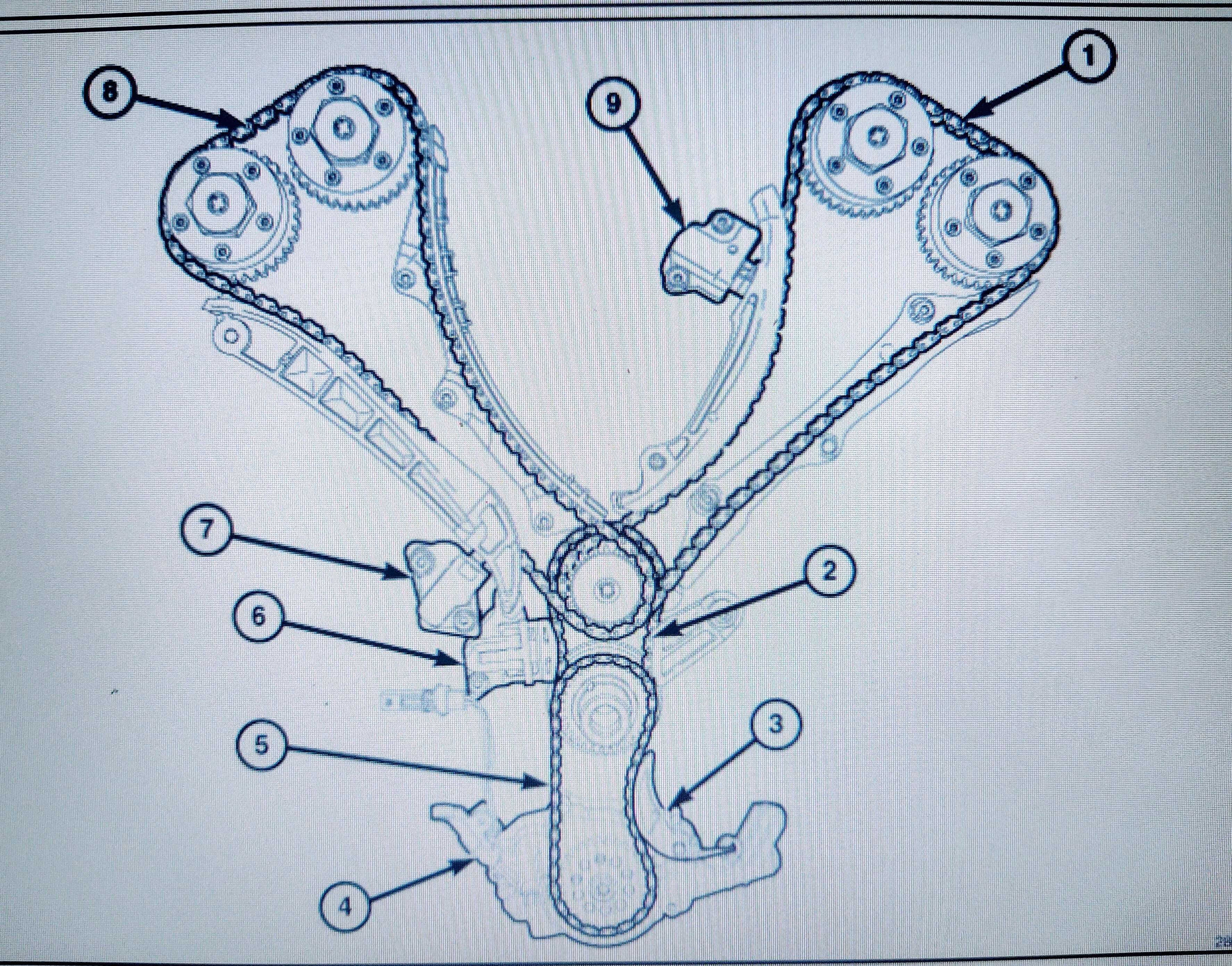
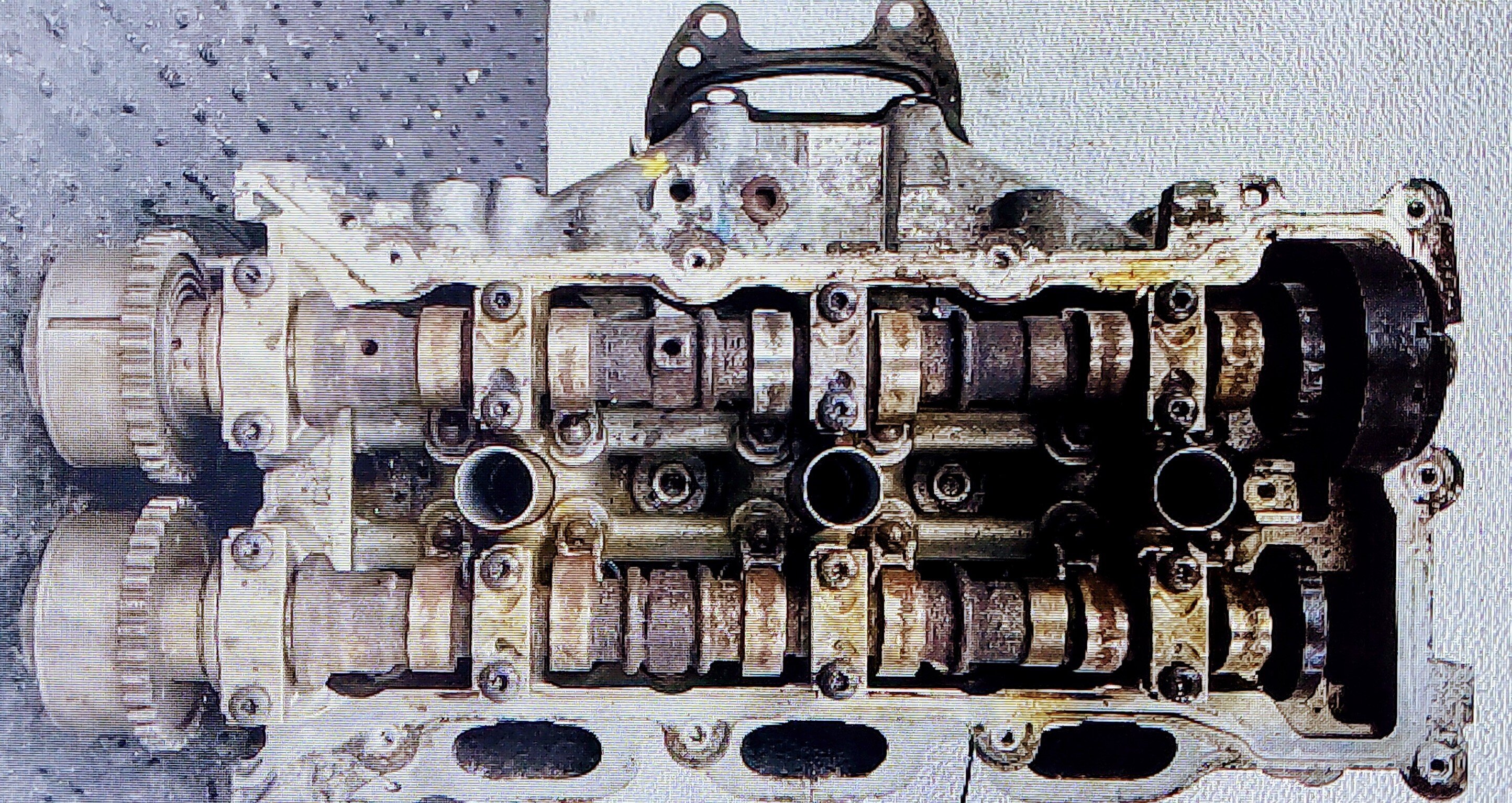
A cars fluids is something you should check regularly. The more often you do. The more problems you will prevent or catch before it gets expensive to fix. The 3.6 is a highly complex engine internally. With it's wide engine RPM band. Your going to use oil. The harder you drive it even more so. With the 3.6 you should be checking the engine fluids once a week. It has a maze of heater hoses to watch as well. The 3.6 liter (219.7 CID) flexible fuel V-6 engine features Variable Valve Timing (VVT), Dual Overhead Camshafts (DOHC) and a high-pressure die-cast aluminum cylinder block with steel liners in a 60° configuration. The 3.6 liter engine has a chain driven variable discharge oil pump with a two-stage pressure regulator for improved fuel economy. The exhaust manifolds are integrated into the cylinder heads for reduced weight. This a view of the complex timing chain on the 3.6. This a cylinder head with the valve cover removed. The 3.6 has 2 cylinder heads. Picture the engine spinning up to 5-6,000 RPM's. You got damn lucky in my opinion.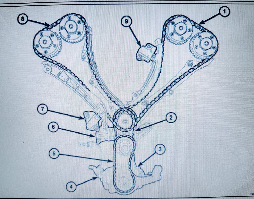

-
2011 R/T relay for heated or power seats?
Dean H replied to Brantbandit's topic in Electrical, Battery & Charging
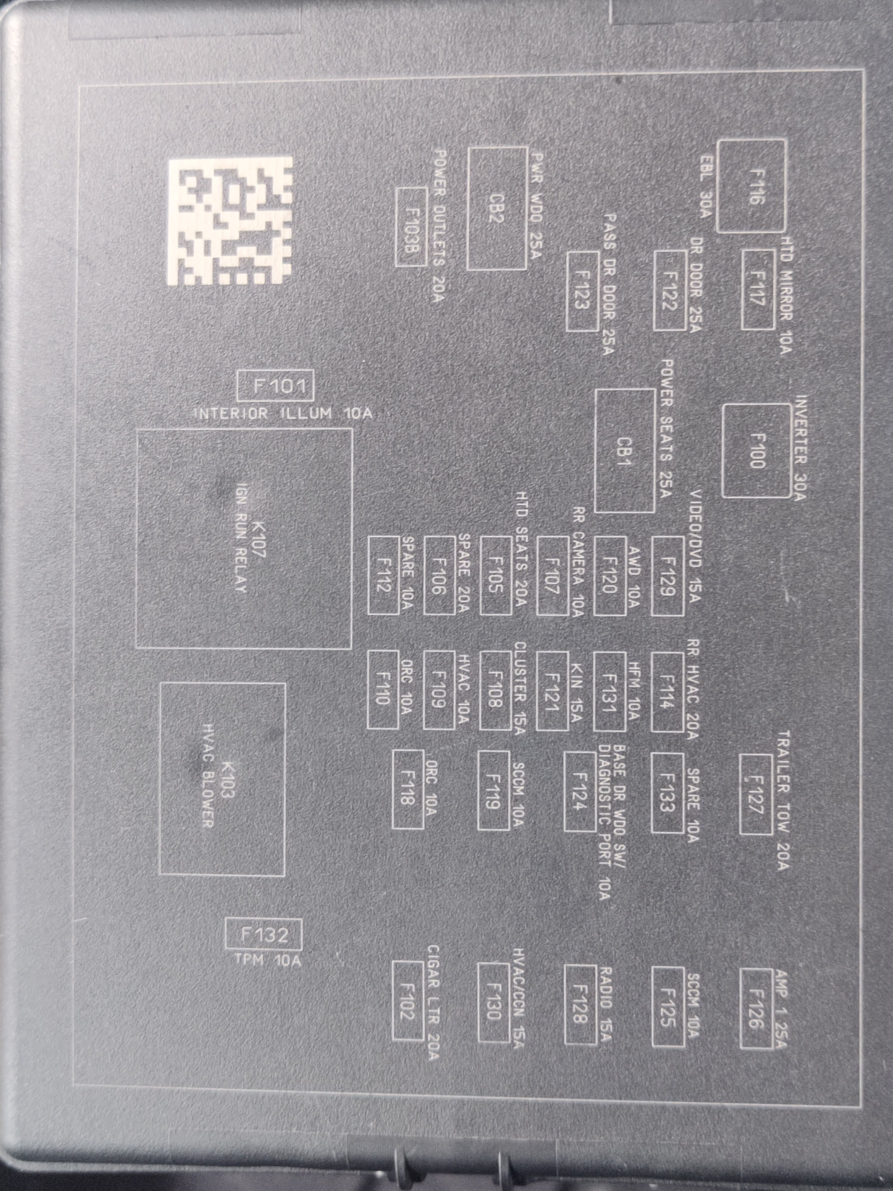
2016 DJ I marked the power seat 25 A CB and the heated seat fuse.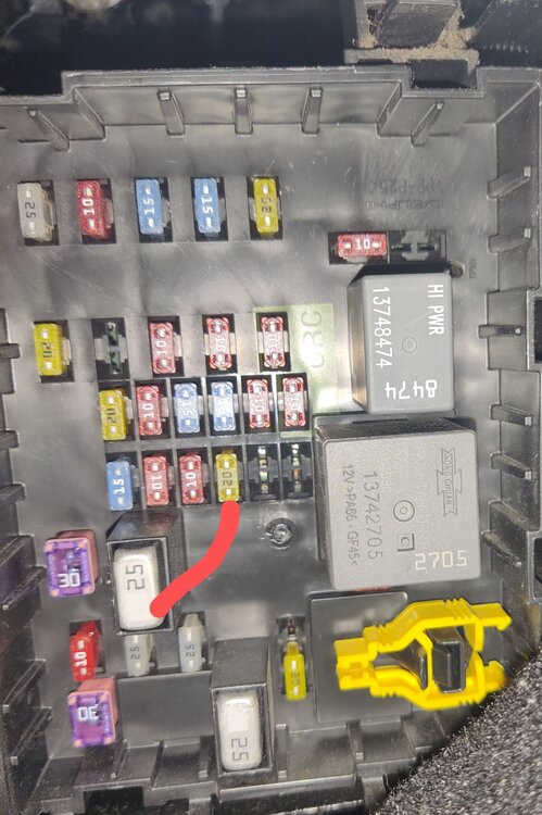

-
Laura, Check your forum inbox. I sent you 2 emails.
-
Electrical System FYI - ground system
Dean H replied to Dean H's topic in Electrical, Battery & Charging
You can buy it on eBay in your length and lug size needed. I have bought from this ebay seller. Who does good work. https://www.ebay.com/str/acdcwireandsupply?mkcid=16&mkevt=1&mkrid=711-127632-2357-0&ssspo=MvbsRTEuTMK&sssrc=3418065&ssuid=i3l8BOlITT-&widget_ver=artemis&media=COPY Or Amazon search for 2 gauge battery cables. -
Power Locks Issue
Dean H replied to dbolack's topic in Alarms, Keyless Entry, Key Fobs, Locks & Remote Start
B2121-15-IGNITION RUN CONTROL 1 - CIRCUIT SHORT TO BATTERY OR OPEN Theory of Operation The Body Control Module (BCM) receives the network communication message from the Radio Frequency (RF) Hub indicating run operation is requested. The BCM provides a voltage output through the ignition run relay control circuit, which connects to the coil side of the Ignition Run Relays. When Monitored: With the Ignition Run Relay off. Set Condition: When the Body Control Module (BCM) detects a high condition on the Ignition Run Relay Control circuit Possible Causes. IGNITION RUN RELAY CONTROL CIRCUIT OPEN IGNITION RUN RELAY CONTROL CIRCUIT SHORTED TO VOLTAGE IGNITION RUN RELAY 1 AND 2 BODY CONTROL MODULE (BCM) B1805-2A-PASSENGER DOOR LOCK/UNLOCK SWITCH-STUCK When Monitored: With the ignition on Set Condition: This DTC will set if the BCM detects the Passenger Door Lock/Unlock Switch stuck in the LOCK or UNLOCK position Possible Causes- PASSENGER WINDOW/DOOR LOCK SWITCH -
Power Locks Issue
Dean H replied to dbolack's topic in Alarms, Keyless Entry, Key Fobs, Locks & Remote Start
B156D-00-LOW VOLTAGE DIFFERENTIAL SIGNAL (LVDS) VIDEO CABLE Set Condition: The Integrated Center Stack (ICS) detects that the Low Voltage Differential Signal (LVDS) Video Cable is disconnected for greater than 10 seconds. Possible Causes LOW VOLTAGE DIFFERENTIAL SIGNAL (LVDS) VIDEO CABLE DISCONNECTED OR DAMAGED TELEMATICS GATEWAY (TGW) INTEGRATED CENTER STACK (ICS) SCREEN MODULE 1.CHECK THE VIDEO CABLE CONNECTIONS AT THE INTEGRATED CENTER STACK (ICS) SCREEN MODULE --------- B16F7-15-FRONT LEFT FOG LAMP CONTROL - CIRCUIT SHORT TO BATTERY OR OPEN Theory of Operation The Body Control Module (BCM) receives the input from the headlamp switch requesting fog lamp illumination. The BCM provides a pulse width modulated (PWM) voltage output through the fog lamp driver circuit, which connects to the Fog Lamp. A ground path for the lamps is present through the harness to the body sheet metal. When Monitored: With the fog lamps active. Set Condition: When the Body Control Module (BCM) detects a high condition on the Left Front Fog Lamp Driver circuit. Possible Causes LEFT FRONT FOG LAMP DRIVER CIRCUIT OPEN LEFT FRONT FOG LAMP DRIVER CIRCUIT SHORTED TO VOLTAGE GROUND CIRCUIT OPEN LEFT FRONT FOG LAMP BULB BODY CONTROL MODULE (BCM) -
What engine 2.4 or 3.6 ? Have you tried disconnecting the negative battery terminal and waiting a few minutes, to reset the PCM? P0420-CATALYST EFFICIENCY (BANK 1) Theory of Operation- The State of Change (SOC) catalyst monitor uses the signals from both the upstream and downstream 02 Sensors to detect aging of the catalyst. Based on the fact that when a catalyst ages, it loses some of its Oxygen Storage Capacity (OSC). As a result, part of the untreated exhaust gases can breakthrough the catalyst and causes the downstream O2 Sensor to deviate from its neutral (Stoichiometric) position. By observing the activities in the downstream O2 Sensor signal, located in the exhaust path behind the Catalytic Converter, the degradation level of catalyst can be detected. In general, the higher the downstream O2 Sensor SOC value, the more exhaust gas breakthrough and the lower the Oxygen Storage Capacity of the Catalytic Converter. The Downstream O2 Sensor response monitor is intended to diagnose a Downstream O2 Sensor that is not moving or stuck in a voltage window and to insure accurate information for catalyst monitor diagnosis. POSSIBLE CAUSES: NOTE: A new rear O2 Sensor along with an aging front O2 Sensor may cause the DTC to set. NOTE: If an O2 Sensor DTC set along with the Catalytic Converter Efficiency DTC diagnose the O2 Sensor DTCs before continuing. NOTE: Check for contaminants that may have damaged the O2 Sensor and Catalytic Converter: contaminated fuel, unapproved silicone, oil and coolant, repair necessary. 02 SENSOR 1/1 RETURN CIRCUIT SHORTED TO GROUND 02 SENSOR 1/2 RETURN CIRCUIT SHORTED TO GROUND 02 SENSOR 1/1 RETURN CIRCUIT OPEN 02 SENSOR 1/2 RETURN CIRCUIT OPEN EXHAUST LEAK ENGINE MECHANICAL CONDITION AGING 02 SENSOR CATALYTIC CONVERTER
-
Brake Fluid leak front by bumper
Dean H replied to Tiver43809's topic in Brake, Chassis & Suspension
P0117-ENGINE COOLANT TEMPERATURE SENSOR CIRCUIT LOW Theory of Operation The Engine Coolant Temperature (ECT) Sensor is a variable resistor that functions as a normal two wire, 5 volt sensor. The PCM supplies the ECT Sensor with a 5 volt reference and a filtered ground (return) circuit. For the ECT Sensor diagnostic, the PCM internally monitors the voltage on the signal circuit, which is converted into a temperature reading. If the voltage reads above the high calibrated threshold, or below the low calibrated threshold, a circuit high or low fault is set. When Monitored and Set Conditions When Monitored: This diagnostic runs continuously when the following conditions are met: With the ignition on. Battery voltage greater than 10.4 volts. Set Conditions: The ECT Sensor input voltage is below the minimum acceptable value. Default Actions: The MIL light will illuminate. The ETC light will illuminate. Throttle input and vehicle speed are limited. Possible Causes ECT SIGNAL CIRCUIT SHORTED TO GROUND ECT SIGNAL CIRCUIT SHORTED TO THE SENSOR GROUND CIRCUIT ENGINE COOLANT TEMPERATURE (ECT) SENSOR POWERTRAIN CONTROL MODULE (PCM