Dean H
-
Posts
269 -
Joined
-
Last visited
-
Days Won
31
Content Type
Profiles
Forums
Gallery
Everything posted by Dean H
-
Brake Fluid leak front by bumper
Dean H replied to Tiver43809's topic in Brake, Chassis & Suspension
P0113-INTAKE AIR TEMPERATURE SENSOR 1 CIRCUIT HIGH Theory of Operation The Intake Air Temperature (IAT) Sensor is a variable resistor that functions as a normal two wire, 5 volt sensor. The Powertrain Control Module (PCM) supplies the IAT Sensor with a 5 volt reference and a filtered ground (return) circuit. For the IAT Sensor diagnostic, the PCM internally monitors the voltage on the signal circuit, which is converted into a temperature reading. If the voltage reads above the high calibrated threshold, or below the low calibrated threshold, a circuit high or low fault is set. When Monitored: This diagnostic runs when the following conditions are met: With the ignition on. Battery voltage greater than 10.4 volts. Set Conditions: The PCM detects that the IAT Sensor input voltage is above the maximum acceptable threshold. Default Actions: MIL light will illuminate. POSSIBLE CAUSES IAT SIGNAL CIRCUIT SHORTED TO VOLTAGE IAT SIGNAL CIRCUIT OPEN/HIGH RESISTANCE SENSOR GROUND CIRCUIT OPEN/HIGH RESISTANCE INTAKE AIR TEMPERATURE (IAT) SENSOR POWERTRAIN CONTROL MODULE (PCM) -
Very Important!! The correct type of ANTIFREEZE! For my 2016 DJ it is a Orange antifreeze. Type called OAT. You need to do a complete refill of the entire system with the pre mixed antifreeze. This is the #1 issue you need to correct. Before you do overheat and cook your engine and transmission!
-
Brake Fluid leak front by bumper
Dean H replied to Tiver43809's topic in Brake, Chassis & Suspension
Ambient air temperature sensor. Mounts behind the lower air intake of the front clip. My 2016 shown below.
-
You need a bi-directional scan tool. Capable of communicating with all of the electronic modules. 2016 DJ CODE INFORMATION: U0002-88-CAN C BUS OFF PERFORMANCE - BUS OFF. When Monitored: This diagnostic runs continuously when the following conditions are met Ignition on. No under voltage codes. Set Conditions: Anti-lock Brake Module (ABS) Module detected a catastrophic failure on the CAN bus. Default Actions: ABS is disabled. Possible Causes: CAN BUS CIRCUITS OPEN OR SHORTED. CODES RELATED TO BATTERY VOLTAGE, IGNITION, OR VIN MESSAGES. BODY CONTROL MODULE (BCM) POWER AND GROUND. BCM NOT CONFIGURED CORRECTLY. BODY CONTROL MODULE (BCM). MODULE THAT SET THIS DTC.
-
I have the manual HVAC system.
-
Welcome! What engine do you have 2.4 4 cyl or 3.6 6 cyl? Maintenance items: 1) cabin filter behind glove box. 2) correct transmission fluid and filter service. ****HIGH PRIORITY***** https://www.dodgejourneyforum.com/topic/18151-automatic-transmission-fyi-please-read/ 3) AC evaporator drain clean out. https://www.dodgejourneyforum.com/topic/17985-easy-ac-drain-clean/ 4) Electrical system. Getting to know it and understand it. Before the issues begin. https://www.dodgejourneyforum.com/topic/18210-electrical-system-fyi-battery/ https://www.dodgejourneyforum.com/topic/18374-electrical-system-fyi-ground-system/
-
On my 2016 DJ. On the touch screen go to rear climate controls. Push rear controls off. Push rear controls locked out. or Pull the fuse for the rear HVAC controls. Interior fuse panel.
-
Not all doors lock
Dean H replied to Dilshod NIyozov's topic in Alarms, Keyless Entry, Key Fobs, Locks & Remote Start
Few questions....... What is the history of the problem? Any vehicle history that may have caused the issue? Has the FOB locked all the doors correctly ever? Does the interior door lock switch lock all the doors? Does the exterior door handle button lock all the doors? -
Dodge specs 2016 3.6 engine. -Thermostat opens 195 F. -No AC on. radiator fan turns on 220 F. fan turns off 214 F. -AC ON. fan runs continuously controlled by PCM. -Transmission oil temperature Fan on 232 F. -Transmission oil temperature overheated - 240 F. My 2016 3.6. Runs to the specs listed above. My transmission oil temperature always runs around 175 F max. I have new transmission fluid and filter. Serviced 5k miles ago. I reside in the US. Current daytime outside temperature mid 90's F. I run max ac constantly with no problems.
-
First, do you know how to select the available gauges on the display screen located between the speedometer and tachometer? Under vehicle info on the screen menu there are several engine gauges to display. Find the engine coolant and transmission fluid temperature gauges. We need to know what your engine coolant temperatures are first. Determine, if the cooling system is working correctly. What are the transmission fluid temperatures at the same time. When it's overheating.
-
Post good clear pictures of the wires and location.
- 1 reply
-
- 1
-

-
https://www.dodgejourneyforum.com/topic/17786-android-radio-installed-working-ac-steering-controls-everything/
-
Thanks! For catching that and clarifying the scan tool needed. Dean
-
Read my post here- https://www.dodgejourneyforum.com/topic/18560-no-bus-indicator/
- 1 reply
-
- 1
-
-
NO BUS INDICATOR DJ 2016 service CD IC = instrument cluster The no bus indicator gives an indication to the vehicle operator when the IC detects a loss of electronic communication over the CAN data bus. This indicator is controlled by the IC logic circuit based upon programming and electronic messages not being received over the CAN data bus from the BCM. The no bus indicator function of the electronic display unit is completely controlled by the IC logic circuit, and that logic will only allow this indicator to operate when the IC receives a battery current input on the fused ignition output (run-start) circuit. Therefore, the no bus indication will always be OFF when the ignition switch status is anything except ON or START. The IC will turn ON the no bus indicator for the following reasons: • No Electronic Communication Messages - Each time the ignition switch is turned to the ON position and the IC does not receive electronic communication messages over the CAN data bus, the no bus indicator is illuminated. The indicator remains illuminated until CAN bus communication is restored or until the ignition switch status transitions to OFF, whichever occurs first. The IC continually monitors the CAN data bus to determine the status of many sensors and systems throughout the vehicle. If the IC detects the loss of CAN bus communication it illuminates the no bus indicator to alert the vehicle operator that it cannot provide accurate displays and outputs. For proper diagnosis of the IC, the CAN data bus or the electronic communication related to no bus indicator operation a diagnostic scan tool is required.
-
C0030-02- LEFT FRONT TONE WHEEL - GENERAL SIGNAL FAILURE Set Conditions: Anti-lock Brake System (ABS) Module detects periodic drops of a Wheel Speed Sensor (WSS) signal Default Actions: ABS is disabled. Possible Causes- LEFT FRONT TONE WHEEL/BEARING DAMAGE IMPROPER LEFT FRONT TIRE PRESSURE/MISMATCHED TIRES DEBRIS IN TONE WHEEL/BEARING/SENSOR OR DAMAGED
-
1) Battery saver mode = weak battery. Get battery auto technician tested. 2) Automotive shop to scan the system for codes. Parts store scan is probably a basic scan. Not enough for you.
-
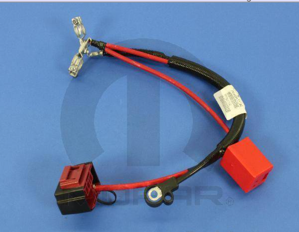
I looked up the battery cables for the 2010 DJ. 2.4 and 3.5 engines. The ground cable is separate. Simple to replace go standard 2 AWG cable. Critical factor - The positive cables you need to see how they connect inside the plastic connectors. If you do have this cable arrangement. Get the best pictures of the red cable inside the plastic connectors. See if it is lug ends connected to a bolt. You could put a set together. Complete stock cable harness starts at $155.00.
-
You have 2010 Journey? My 2016 DJ is different than yours regarding cable connections. Post a picture of driver's side strut tower. Where the negative battery cable connects. I believe the battery positive cable connects on the strut tower, as well.
-
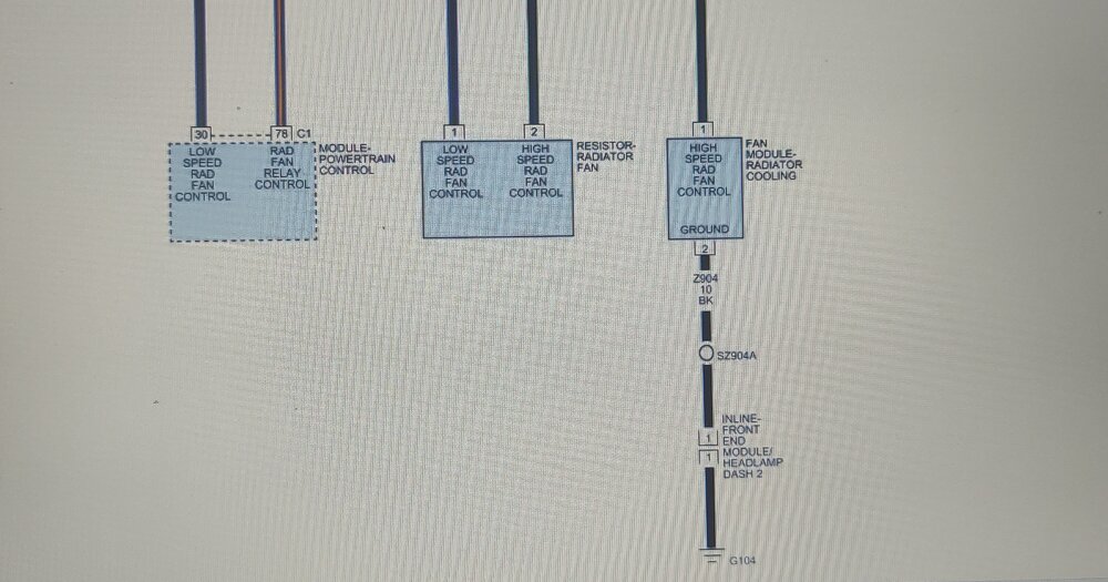
First thing for auto parts go to Rock auto.com. They have everything you might need at the lowest cost. You pay a flat fee for shipping from each warehouse your parts come from. I use Rock auto exclusively. For reference and research as well. https://www.rockauto.com/ Your 100% correct regarding the fan operation. Only AC high pressure turns the fan on. I found the Fan operation information. Theory of Operation The two speed cooling fan system uses two relays and a radiator fan resistor to control the cooling fan operation. The two relays are the High Fan Relay, Lo-Hi Fan Relay. During low speed mode, the cooling fan operates in series with the Radiator Fan Resistor, limiting the 12 Volt source to the Radiator Fan Module. During high speed mode, the cooling fan motor receives a battery voltage feed directly from the High Speed Radiator Fan Relay. During low speed mode: The PCM grounds the (N201) Fan Relay Control circuit, closing the relay to connect the Cooling Fan 12 Volt Supply circuit to the (N23) Cooling Fan Motor 1 Output circuit. The (N23) Cooling Fan Motor 1 Output circuit supplies 12 Volts to the Radiator Fan Resistor. Current flows through the resistor and out the (N24B) Radiator Fan Relay Output circuit. The current is sent back to the PDC and is spliced into the (N24A) Radiator Fan Relay Output circuit which goes directly to the Radiator Fan Module. The (Z904) Ground circuit provides the ground path for the Radiator Fan Module During High speed mode: The PCM grounds the (N112) Rad Fan Relay Control circuit and the (N112) Fan Relay Control circuit, closing the High Speed Radiator Fan Relay. The Cooling Fan 12 Volt Supply circuit connects to the (N24A) Rad Fan Relay Output circuit and provides 12 Volts to Radiator Fan Module. The (2904) Ground circuit provides the ground for Radiator Fan Module
-
Codes P0480 - P0481 . Cooling fans 1 and 2 relay control circuit open. Causes - -fan Relay -fan relay control circuit open -fan relay control circuit shorted to ground. Your coolant temperature sensor is working fine. Using the digital coolant temperature gauge. You can see when the fan kicks on dropping the temperature. My DJ, fan kicks on at 220 F cools down to 210 F. The analog temperature gauge always stays a hair left of the center line. Thermostat Operation - Rated temperature 195 F. The thermostat is designed to guarantee a minimum engine operating temperature of 88 to 93°C (192 to 199°F). The thermostat also will automatically reach wide open so it will not restrict flow to the radiator as temperature of the coolant rises in hot weather to around 104°C (220°F). Above this temperature the coolant temperature is controlled by the radiator, fan, and ambient temperature, not the thermostat. Fan specifications - Cooling fan wiring diagram - The water pump heater hose inlet possible obstruction, is something I read online. Found the piece in the Service CD. I haven't checked YouTube.


-
Headlight relay/fuse problem - 2010 dodge journey SXT
Dean H replied to Katlyn's topic in Electrical, Battery & Charging
Maybe it's the common problem of the 09-10 DJ TIPM relays that are soldered to it going bad. Ask here. https://circuitboardmedics.com/2009-2010-dodge-journey-tipm-repair-service/?srsltid=AfmBOopx7YC9nMaSqJdN8RX9N6_WtCWAHcKhGUJ7jlPjQfsl50gQnwo5 -
Headlight relay/fuse problem - 2010 dodge journey SXT
Dean H replied to Katlyn's topic in Electrical, Battery & Charging
okay, That fixed Krishelle's DJ. So on the 2010 DJ, There is no separate light switch. Everything is on the turn signal switch on the steering column. Have you been able to locate a fuse or relays under the hood or interior fuse box? Need to get a copy of the correct 2010 wiring diagram. For all lighting systems. Ask a shop if they would get them for you. My information is for a 16 DJ. Dean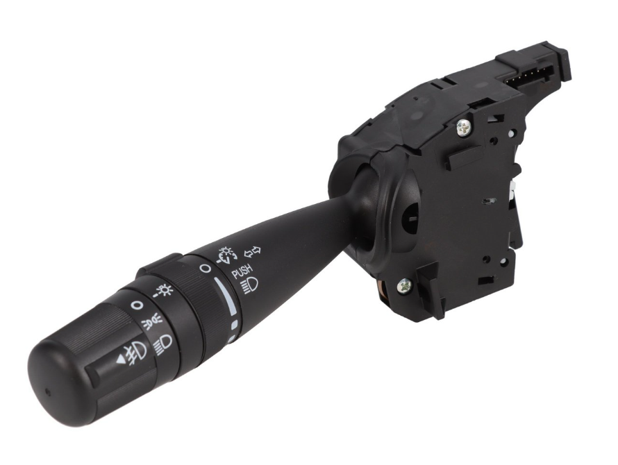
-
Headlight relay/fuse problem - 2010 dodge journey SXT
Dean H replied to Katlyn's topic in Electrical, Battery & Charging
Katlyn, Replace the turn signal lever-switch. -
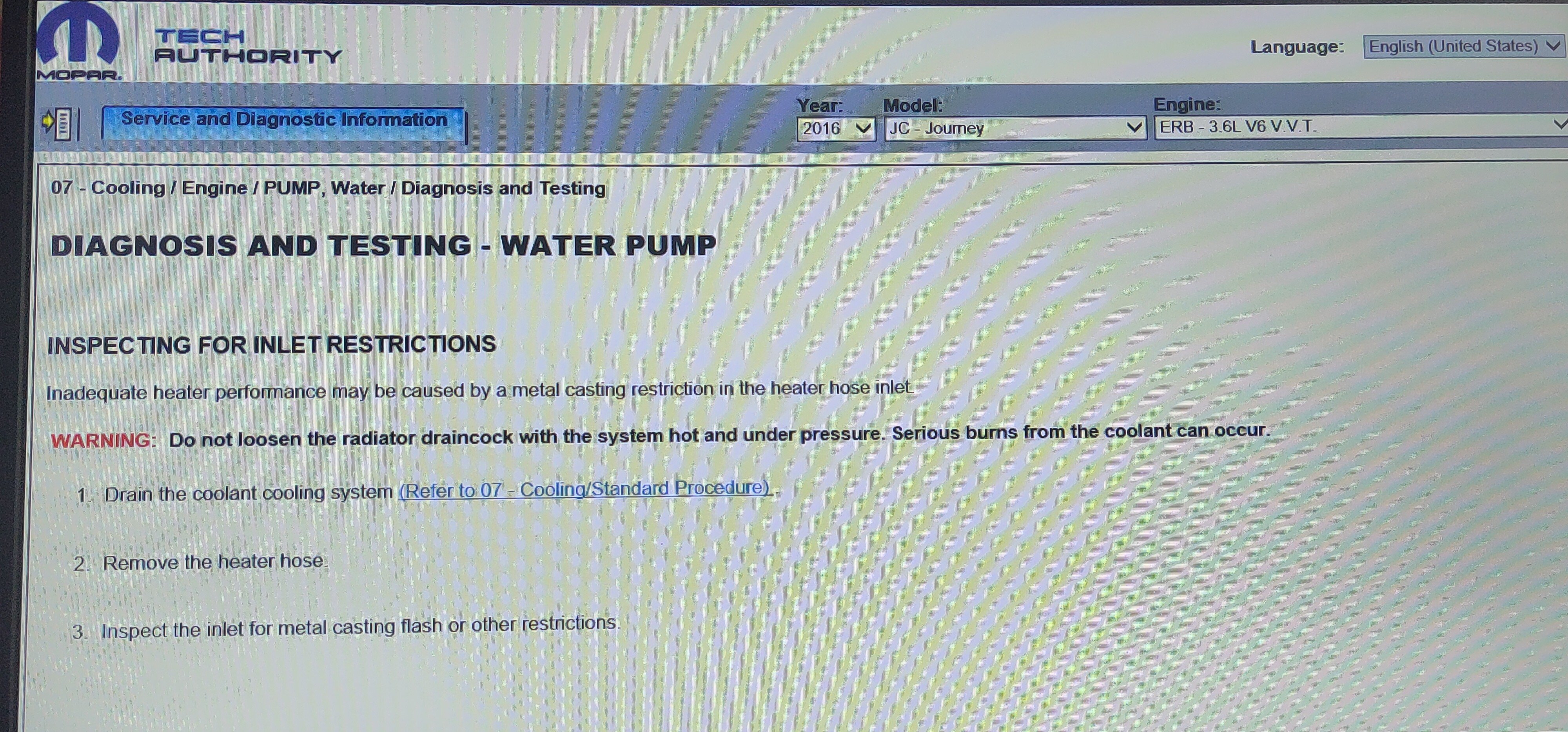
If you have the instrument cluster below on the DJ. Use the steering wheel keypad arrows and back button. To access any available gauges in the menu. Flow chart 3.6. 1 - RADIATOR 2 - RH CYLINDER HEAD 3 - THERMOSTAT 4 - WATER CROSSOVER 5 - LH CYLINDER HEAD 6 - REAR HEATER CORE 7 - FRONT HEATER CORE 8 - OIL COOLER 9 - WATER PUMP 10 - CYLINDER BLOCK I found this on the 2016 DJ service CD. The heater hose connection by the lower engine radiator hose on the water pump. May have a restriction in it that affects heater core performance. Read below-